Editing notes
Google search index set to off temporarily
Purpose This page is to introduce types of inspections services provided by Caspian.
Loss of section testing box – changed to shorter sentences.
Add link to a new page on stand off base plates, anchor bolt fatigue cracking etc.
Add section on rating – see KIWA docs ISO/IEC 17025
Other pages being edited (Not linked to existing pages)
Street Lighting Inspection and Structural Testing
Caspian NDT provide Non Destructive Testing services for street and highway lighting structures throughout the UK.
We provide Street Lighting Inspection and Structural Testing services for both the public and private sectors. Our clients include local authorities, contractors, schools, retail parks, motorway service areas, airports around the UK.
Street lighting structures operate in a corrosive environment while simultaneously being subjected to dynamic wind loads.
Street lighting structures could be either free-standing column or parasitic. Free-standing columns include planted (rooted) and flanged. Parasitic lighting structures could be attached to buildings, bridges or any other suitable locations.
Planted (rooted) are columns whose base is inserted directly into the ground without a foundation.
Flanged columns are fitted with a welded end plate. The end plate is then bolted to a concrete foundation, a bridge or other structure.
High Mast Light Poles (HMLP) is the term used to describe the tallest type of light pole. HMLPs are typically 20 – 35 m high. See High Mast Light Pole Inspection
Note! Many lighting structures are now being supplied or retrofitted with low energy luminaires. Low energy luminaires can be heavier than the incandescent sodium lamps previously used.
Material loss due to corrosion and cracking caused by fatigue can significantly reduce the life of the asset and increase risk to the public.
Measurement of material loss caused by corrosion enables the remaining safe life and maintenance requirements of the asset to be determined.
Caspian NDT use the following methods to measure material loss, locate defects and to assess safe remaining life of lighting columns.
1. Visual Examination
2. Ultrasonic Testing (UK)
3. Special purpose Eddy Current Testing
4. Magnetic Particle Inspection (MPI)
5. Dye penetrant Inspection (DPI)
6. Reporting and assessment
1. Visual Examination
In many cases, specialist tools are not required to identify defects that could compromise the structural integrity.
Visual examination is often the simplest and quickest method to judge the conditions of the asset. A detailed visual examination can be used to identify any visible defects that would compromise structural and functional integrity. For example, corrosion, mechanical damage, loose and missing fasteners etc.
Visual examination can be just be simple observation. A more detailed visual examination could use a microscope, magnifying glass or other methods of image enhancement.
Boroscopes are used for internal examination or locations that are difficult to access.
A range of measuring equipment is used to assess the extent and shape of any defect. e.g. Tape measures, ultra sonic thickness meters, digital calipers, micrometers, laser levels, laser measuring devices etc.
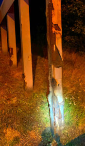
Fig 1.1 Corroded road sign support column
Excessively corroded motor way sign support. The most corroded leg shown here is the closet to the carriage way. Proximity to the carriage way and zone of salt spray has accelerated the rate of corrosion
Fig 1.2 Excessively corroded access opening in lighting column
The extent and location of the corrosion further weakens the access opening.
Deformation of the right side of the door opening indicates a substantial impact. The deformation further the access opening. The combination of corrosion and deformation reduce the structural strength and stability of the lighting column as a whole.
It is also noted that this lighting column has been incorrectly installed. i.e. The lighting column has been planted too deep into the ground. The installation depth put the weakest part of the column into the zone with the highest expected rates of corrosion.
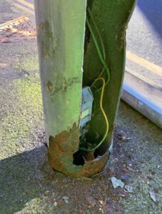
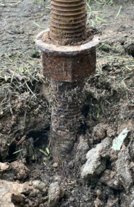
Fig 1.3 Corroded holding-down bolt previously used to support a stand-off base plate. Draft High Mast Light Pole Inspection
This photographs indicates two main problems
1. The holding-down bolt threads below the “levelling nut” are in direct contact with the soil. Soil is often damp and oxygenated near its surface thus creating a perfect environment for accelerated corrosion.
2. The structure supported by this holding-down bolt was incorrectly installed. The supported structure is therefore weaker and less able to withstand wind and other external loads. The design of stand-off base plates is based on the assumption that the distance between top of concrete and underside of levelling nut is not greater than the bolt diameter. It is assumed that bending stress in the holding-down bolt can be ignored if the clear distance is less than1 bolt diameter. Bending stresses in this bolt cannot be ignored.
2. Ultrasonic Testing (UT
Ultrasonic testing (UT) can be used to detect several types of defect.
i) Measurement of wall thickness loss due to corrosion at any location above ground level.
ii) Detection of sub-surface weld cracks, lack of weld fusion, material delamination and other internal defects.
iii) In-situ measurement of corrosion and fatigue cracking of anchor bolts and fasteners. UT is the only practical method that can be used to assess the condition of anchor bolts and fasteners without disassembly and unloading of the joint.
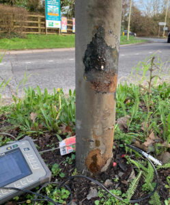
Fig 2.1 Ultrasonic Testing (UT) thickness testing of a corroded lighting column.
Corrosion is often, but not always, the most severe at soil level.
Gel is applied to the area to ensure good acoustic contact and accurate results.
Fig 2.2 Ultrasonic Testing of bar stock to confirm the absence of internal defects
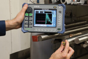
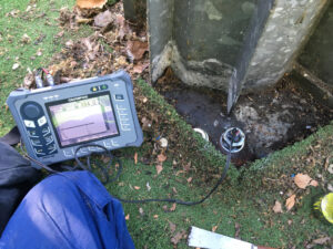
Fig 2.3 Ultrasonic testing of an anchor bolt
Anchor bolts in this type of location often use levelling nuts rather than structural grouting. Absence of fully sealed structural grouting can often increase rate of anchor bolt corrosion below the base plate.
The absence of preload below the levelling nuts increases the risk that the anchor bolt will be subject to fatigue cracking. See Draft High Mast Light Pole Inspection.
3. Special Purpose Eddy Current Testing
Caspian NDT use a Colchek2® special purpose eddy current testing machine to detect below ground corrosion of planted (rooted) lighting columns.
The Colchek2® can detect loss of wall thickness to an accuracy of about 5% to a depth of 750 mm below ground level.
The Colchek2® consists of an above ground driver coil and an internal detector coil. The drive coil surrounds the column at ground level. The drive coil induces a current in the the lighting column wall. A detector coil is then inserted into the column. The wall thickness is measured at the depth of the detector coil.
The Colchek2® machine allows wall thicknesses to be measure to a sufficient accuracy without the need to excavate the pavement.
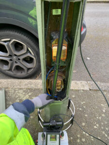
Fig 3.1 A lighting column being checked with a Colchek® special purpose eddy current machine.
A Colchek® machine with drive coil is shown resting on the pavement at ground level.
A detector coil attached to a black probe is shown being inserted into the lighting column access opening.
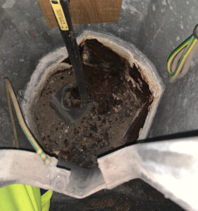
Fig 3.2 View looking downwards into a planted (rooted) lighting column
The base of lighting columns are normally partially blocked to the prevent the entrance of surrounding material.
The electrical power supply normally enters column via a second wall access opening below ground. Vertical penetration of the cable into the soil would indicate that soil has been washed into the column. The soil would need to be cleared to allow full access to the entire column by the detector coil.
Very significant corrosion can be seen to the right side of the power cable. The patten of rust debris indicates that the column wall has been breached by corrosion thus allowing soil entry.
4. Magnetic Particle Inspection (MPI)
Caspian NDT use Magnetic Particle Inspection (MPI) to locate and measure sub-surface defects in steel and magnetic materials. Defects detectable by MPI could be caused by weld imperfections, fatigue cracks, internal defects and physical damage.
MPI involves coating the area with a fluid containing magnetic particles. The particles are aligned and concentrated on discontinuities in a magnetic field caused by underlying material defects. The magnetic field is induced by an electromagnet.
Typical locations for defects include columns welds, including swage weld, tube-to-flange welds, attachment bracket welds, corners of access doors, stress concentrations caused by gussets etc.
MPI has the advantage that the surfaces being tested do not need to be smooth or free from paint, rust or other coating.
See BI NDT (The British Institute of Non-Destructive Testing) for more details.
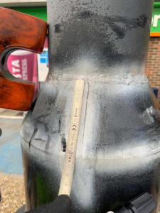
Fig 4.1 Detection of a weld crack in the reducing section in lighting column highlighted using MPI
The area being tested is sprayed with white contrast paint prior to application of the detection fluid. The white paint enhances the visibility of the magnetic particles.
The defect shown could be the result of weld sidewall fusion when the lighting column was first manufactured. i.e. The operating stresses in the longitudinal weld are less than those in the circumferential welds.
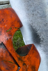
Fig 4.2 Detection of a crack running from the toe of a lighting column attachment weld using MPI.
The crack location is typical of a fatigue crack which started at the toe of a weld. Weld toes often create both a geometrical and metallurgical stress concentration which accelerates the growth of exiting micro crack in the weld or which encourages a new crack to begin.
4. Dye Penetrant Inspection (DPI)
Dye Penetrant Inspection (DPI) is used for the detection of surface breaking defects.
DPI is more often during manufacturing or repair rather than for routine field inspection. i.e. DPI requires much more surface preparation than for Magnetic Particle Inspection (MPI).
Surface preparation for DPI requires cleaning, removal of paint and degreasing. All welds must be ground to create a smooth surface and profile.
A very low viscosity and highly penetrating dye is then applied to the surface. The dye will soak into any surfaces cracks and defects.
Excess dye is wiped off before an absorbent white paint is applied. Dye that has been trapped in a crack wicks into the coating thus highlighting the crack location.
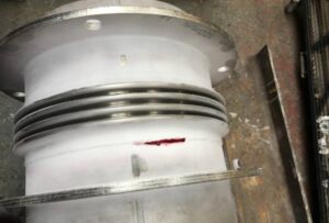
4.1 Example of Dye Penetrant Inspection (DPI)
Dye Penetrant Inspection of a shop weld identifying a cracked weld
Loss of section testing
High levels of corrosion which than can critically weaken structures often occurs at and just below ground level.
Planted lighting columns are often at the greatest risk of corrosion caused by high levels of chlorides, and moisture.
Specialist Non-Destructive Testing
Our Specialist NDT division covers the Non-Destructive Testing of High Masts, Floodlights, Flanged and Bridge mounted columns, Traffic Mast Arms, Motorway Safety Barriers and other metal structures.
Electrical Testing
To maintain the integrity of our testing activity, all work is carried out by our fully qualified engineers to ensure compliance with current regulations. IEE Regulations requires periodic inspection and testing of lighting installations.