1 Objective
The notes explains why the regular inspection of high mast light poles is so important to ensure public safety.
2 What are High Mast Light Poles?
A High Mast Light Pole (HMLP) is a flange mounted lighting column. HMLPs are used for the tallest type of lighting column typically from 15 m to 60 m. An HMLP typically carries a multi-element luminaire.
HMLPs are normally used to illuminate larger areas with the fewer lighting columns than used for normal street lighting. For example, Airports, motorways, retail parks, flood lights etc.
HMLPs that are installed using stand-off baseplates create a unique risk of failure. (See Fig 1 below). This page discusses the associated operational risk and how these risks can be managed.
This discussion only applies to HMLPs installed on stand-off base-plates.
3 High Mast Light Poles (HMLP) design
3.1 Design Challenges
a) Consequences of failure
HMLPs are normally located in high traffic, high occupancy areas where consequence of collapse would be particularly severe.
b) Unpredictable safe operating design life
It is impossible to calculate or predict the safe operating design life of the holding-down bolts in an HMLP stand-off base plate when subject to cyclic loads. See below
c) Wind loads
HMLPs are tall and often carry large multi-light element lumaires. The luminaires are normally heavy and have large area subject to wind. HMLP columns are subject to very significant wind loads.
d) Corrosion
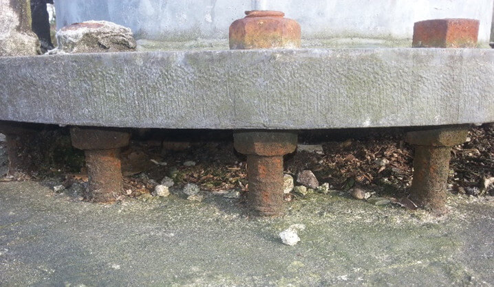
The HMLP holding-down bolts can be subject to potentially high levels of corrosion. Risk of corrosion is increased when the holding-down bolts are covered in soil, vegetation, pooling water or road salt. [See Fig 4 below].
e) Increased base plate flexure and stress
Stand-off base plates are at increased risk of fatigue stress because the flange ring is supported only at its bolts rather than uniformly across is lower face. Supportig only at the holding-down bolts allows flange to flex. The base plate flexure is much more than for an equivalent base plate supported over its complete surface using structural grout and preloaded bolts. The increased flexure causes higher peak stresses and hence a greater risk of fatigue failure. Higher peak stresses often occur at the tops of flange gussets. [See Figs 5 and 6 below for comparison]
3.2 Design
Stand-off base plates consist of a flange supported from a number of holding-down bolts cast into a concrete foundation.
Each bolt is fitted with a levelling nut. The levelling nuts allow levelling of the base plate and the creation of a gap between the base plate and top of concrete.
(The gap between top of concrete and flange can be filled with cosmetic non-load bearing grout. However, the presence of cosmetic non-loading bearing grout does not change the following discussion).
The forces and moments imposed on each moment are entirely dependent on the judgement of the installer.
Therefore, it is impossible to predict or measure the forces and moments imposed on individual holding-down bolts.
HMLPs are one of the few types of structure that is designed to impose cyclic loads onto non-pretensioned threads.
The stress range induced in the holding-down bolts is well in excess of the “endurance limit”. The stress range is exceeded even if the forces carried by each bolt were uniform and predictable. (See Fatigue below). In reality, individual holding-down bolts could be subject to more or less loading than others.
The stand-off base plate is NOT a “redundant design”. i.e. The failure of one holding-down bolt would transfer its loads onto adjacent holding-down bolts.
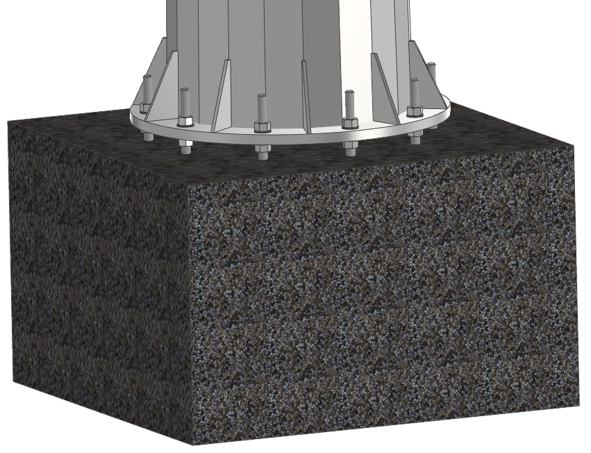
Fig 1 High Mast Light Pole with Stand-off base plate
The design and dimensions used for this examples are typical of commonly used High Mast Light Pole. i.e. The design represented here is NOT based on that of a particular manufacturer.
The holding-down bolts are directly cast into a concrete foundation. See Fig 2 below. Holding-down bolts are not normally sleeved to prevent adhesion with the concrete.
Fig 2 High Mast Light Pole holding-down bolt cage within concrete foundation
Holding-down bolts are typically retained within the foundation using a cast-in retaining ring.
Holding-down bolts are normally cast directly into the concrete without a debond coating or cover to prevent bonding between concrete and bolts, Holding-down bolts could be fully or partially threaded.
Note. All compressive and tensile dead weight and imposed wind loads are transmitted through the holding-down (anchor) bolts.
The section of each holding-down (anchor) bolt below the lower levelling is NOT preloaded.
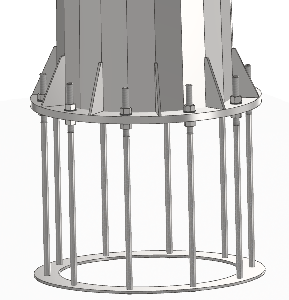
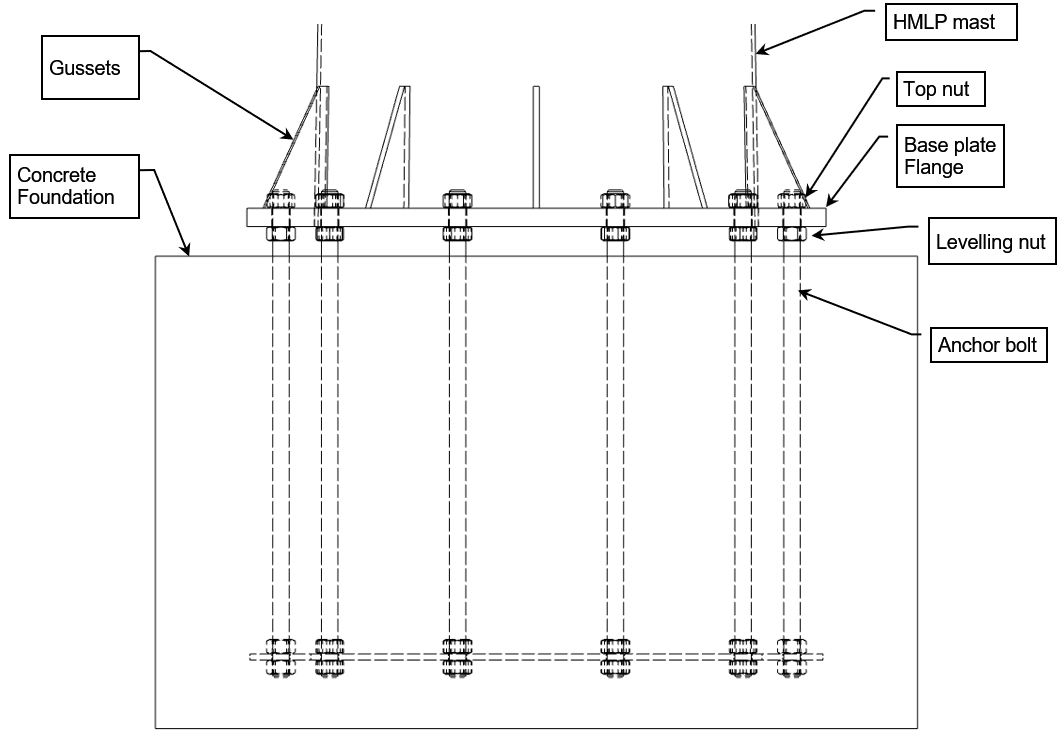
Fig 3 High Mast Light Pole base and holding-down (anchor) bolt notation
Fig 4 Corroded High Mast Light Pole Holding-Down (Anchor) Bolts.
Corrosion has led to a complete loss of threads. The corroded diameter is less that the “stress area” for the size of bolt.
Note also.
1. Aged and ineffective “Denso Tape”.
2. Excessive free height between underside of levelling nuts and concrete. (As a result of sloping concrete surface).
3. Inadequate thread protrusion though the top nut.
Video 1 Failed 35 m High Mast Light Pole Holding Down (Anchor) Bolt.
(Video copyright Caspian NDT)
The middle bolt has failed below below the levelling nut. [See Fig 7 below].
The looseness of all the nuts would imply one of 3 options.
i) The top nuts have loosened. Top nut loosening is unlikely because of the lock-nuts. ***
ii) The bolt has stretched between top nuts and levelling nuts. Stretch is unlikely given the magnitude of the apparent “bolt stretch” over a distance equal to the base plate flange thickness.
iii) The levelling nuts below the base plate flange have self-loosened due to the dynamic wind loads and subsequent oscillation. Self-loosening could be a plausible reason because the levelling nuts are not fitted with lock nuts or locking mechanism.
*** The addition of lock-nuts to the top nuts is futile because it is not practicable to fit locks nuts to the levelling nut!
4 Fatigue cracking and failure of structures
4.1 Fatigue failure
Fatigue failure consists of the cyclic application of loads that are sufficient to initiate and progressively grow cracks in a load bearing material.
Some materials have a minimum stress range known as the endurance limit. e.g. Structural steel. The endurance limit is the stress range below which cracks will not initiate or grow. Materials with an endurance limit are unaffected by cyclic loads and resulting stress ranges below that endurance limit. The rate of crack growth is dependent on the magnitude of the stress range.
A steel structure subject to cyclic or repetitive loading will therefore eventually fail by fatigue if the stress range between maximum and minimum loads exceeds the endurance limit of the material from which the component is fabricated.
The rate of crack growth and hence time to failure depends on:
a) The magnitude of the stress range. A higher stress range will cause a crack to grow by a larger distance for each load cycle.
b) The presence and magnitude of stress concentrations in the high stress areas. e.g. “Sharper” re-entrant corners and flaws would cause higher peak stresses than “rounder” re-entrant corners and flaws for the same load applied to the structure.
c) The number of load cycles at each particularly stress range. Each load cycle greater than the endurance limit could cause some microscopic crack growth.
4.2 Fatigue design of threaded bolt.
The notched shape of bolts threads create a high stress concentration. The size of the stress concentration is affected by its method of manufacture. e.g. Thread rolling creates a lower effective stress concentration than thread machining. However, stress concentrations created in rolled threads are are still high when compared with a similar rod without threads.
The endurance limit for threaded rod is typically very low when compared with the bolt static tensile strength. e.g. About 20 MPa. [BS EN 3 Part 1-9]. The allowable design value for the endurance limit of a thread rod is often independent of bolt static tensile strength. i.e. A high strength bolt could have the same design endurance limit as a low strength bolt – or even lower!
How is it possible that bolts can be used for high cyclic load applications if thread rod has a low endurance limit?
The answer is a paradox. Bolts are often used without risk of failure in high load cycle applications. For example, wheel studs on a motor vehicle. Bolts threads are normally preloaded to ensure that the threads are subject to only a very small fraction of the cycling load applied to the bolted joint. i.e. The stress range in a bolt thread is designed to be much less than its endurance limit.
The bolt is preloaded in excess of any variable loads likely to be imposed during operation of the joint. The change of bolt stress and bolt strain (stretch) will be minimal if the bolted joint does not “open-up” under any operating conditions. Hence, the bolt load remains nearly constant with minimal stress range.
In contrast, the holding-down bolts in an HMLP stand-off base plate cannot be preloaded and thus subject to the full imposed cyclic load.
Fig 5 Finite Element Analysis results for High Mast Light Pole with stand-off base plate.
Note. The dimensions and imposed wind loads are typical of commonly used High Mast Light Poles.
The purpose of this result is for comparison** with an identical High Mast Light Pole but installed with structural grout and with pre-loaded anchor bolts. [See Fig 5 below].
** Precise calculated stress values are unimportant. A key point to note is that the stresses are significantly higher than fatigue stress infinite life endurance limit.
Stresses denoted in red are 200 MPa and above.
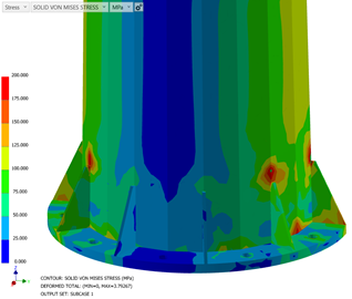
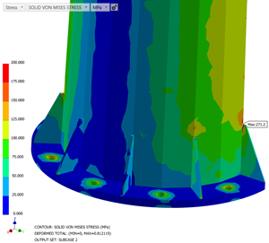
Fig 6 Finite Element Analysis results for High Mast Light pole with structurally grouted based plate and pre-loaded anchor bolts
Note. The dimensions and imposed wind loads are typical of commonly used High Mast Light Poles.
The purpose of this result is for comparison with an identical High Mast Pole using a Stand-off Base Plate. [See Fig 5 above]. The stresses in the two gussets and flange on the right are much lower than those for the stand-off base plate in Fig 5 above.
Precise calculated stress values are unimportant.
Stresses have exactly the same colour scale as Fig 5.
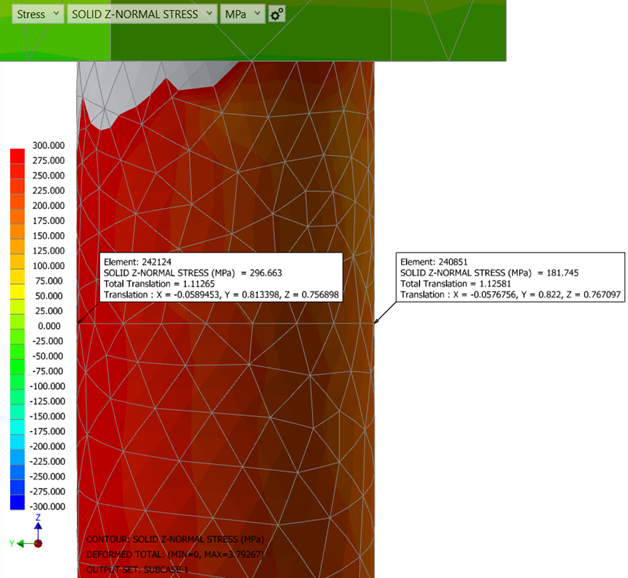
Fig 7 Close up view of Finite Element Analysis results of most highly loaded anchor bolt below the lower levelling nut.
The stress area of the bolt has been used. The purpose of this result is to show that the bolt stresses are relatively high when subject to typical wind loads.
(Relatively high in comparison with allowable endurance limit for bolts threads).
Precise stress values in this example are unimportant. A red colour in this diagram represents calculated stresses of 300 MPa. 300 MPa is reasonable for static loads applied to Grade 8.8 bolts.
Note: 300 MPa is very much higher than that for infinite life (endurance limit) of threaded bolts.
Notes.
1. Calculated stress values in elements touching the intersection of the underside of the levelling are not valid. i.e. The re-entrant “corner” as modelled is a “singularity”. A “singularity” would always display stresses that are incorrectly high.
2. This model does not include the stress concentration of threads. Hence, the calculated stresses displayed are unrealistically low.
6 Failure of structures using stand-off base-plates other than high mast light poles.
6.1 Smaller wind turbines (less than 75 kW approx)
A number of smaller wind turbines using stand-off baseplates have collapsed due to failure of their holding-down bolts below the lower levelling nuts. [Ref 2, Ref 3]. The over-turning and cyclic loads applied to the base plate share many characteristics with High Mast Light Poles.
(Larger wind turbines normally use sleeved holding-down bolts that are post-tensioned over their full length).
Fig 6.1 Collapsed Wind Turbine at Bradworthy [Ref 2]
Note: Most holding-down bolts snapped below the lower levelling nuts as shown by most of the nuts being still connected to the base flange. The foundation for this wind turbine is shown in Fig 6.2 below.
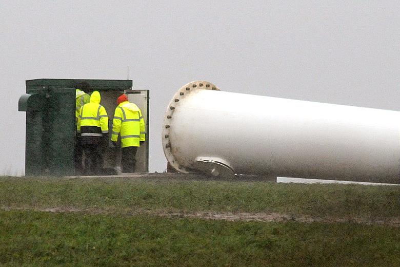
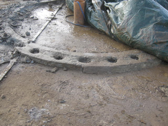
Fig 6.2 Foundation of Bradworthy wind turbine after collapse [Ref 2]
Note: Two holding-down bolts shown near the left side of the photograph have snapped above their levelling nuts. The failure of the bolts above the levelling nuts appears to be consistent with the two missing flange nuts just above ground level in Fig 6.1 above. i.e. All other flange nuts shown in Fig 6.1 above could only be held in in place if retained by their lower levelling nuts. The earthing strip is assumed to directed towards the electrical control cabinet in Fig 6.1.
7 References
1 CROSS Safety Reports
Collaborative Reporting for Safer Structures UK (CROSS-UK).
CROSS maintain a database of reports concerning the safety of structures in the UK
CROSS Safety Reports associated with High Mast Light Poles and related structures
| ID | Description |
|---|---|
| 98 | Unsafe street lighting columns
A report of failure of a cosmetically grouted stand-off baseplate. i.e. Non-structural grout placed under the base plate for appearance rather than the support of structural loads. |
| 315 | Telecommunications towers and resin anchors
Resin fixed holding-down bolts failed after 6 years. (Comment – A stand-off was used for this installation is inferred by the statement “Some of these anchors do not allow for testing and replacement of critical bolts at the superstructure/substructure interface because of levelling nuts below the base plate”. |
| 610 | High mast light poles removed from UK site
Removed from site following an order made by the local authority. (The author of the report had previously informed the site owner but without any success). The holding-down bolts were judged to to be excessively corroded and inadequate nut engagement. |
| 773 | Accelerated corrosion of telecoms mast holding-down bolts
“During an examination of a 20m high telecoms mast, a reporter found that there had been accelerated corrosion of the galvanised holding-down bolts in the gap between the base plates and the concrete foundation slab. The loss of section was found to be around 5mm in less than 10 years. The holding-down bolts were difficult to inspect as the gap between the baseplate and the foundation was less than 50mm”. |
2 HSE Report “Assessment of Endurance Wind Turbine Failure – East Ash Farm, Bradworthy, Devon” 2 December 2013
3 HSE Report “Assessment of Gaia Wind Turbine Failure – Winsdon Farm, North Petherwyn, North Cornwall” 12 September 2013